|
|
|
BASICS OF FIBER OPTIC CABLE
OVER VIEW OF FIBER OPTIC CABLEIn recent years it has become apparent that fiber-optics are steadily replacing copper wire as an appropriate means of communication signal transmission. They span the long distances between local phone systems as well as providing the backbone for many network systems. Other system users include cable television services, university campuses, office buildings, industrial plants, and electric utility companies. • SPEED: Fiber optic networks operate at high
speeds - up into the gigabits A fiber-optic system is similar to the copper wire system that fiber-optics is replacing. The difference is that fiber-optics use light pulses to transmit information down fiber lines instead of using electronic pulses to transmit information down copper lines. Looking at the components in a fiber-optic chain will give a better understanding of how the system works in conjunction with wire based systems. At one end of the system is a transmitter. This is the place of origin for information coming on to fiber-optic lines. The transmitter accepts coded electronic pulse information coming from copper wire. It then processes and translates that information into equivalently coded light pulses. A light-emitting diode (LED) or an injection-laser diode (ILD) can be used for generating the light pulses. Using a lens, the light pulses are funneled into the fiber-optic medium where they transmit themselves down the line. Think of a fiber cable in terms of very long cardboard
roll (from the inside roll of paper towel) that is coated with a mirror. Light pulses move easily down the fiber-optic line because of a principle known as total internal reflection. "This principle of total internal reflection states that when the angle of incidence exceeds a critical value, light cannot get out of the glass; instead, the light bounces back in. When this principle is applied to the construction of the fiber-optic strand, it is possible to transmit information down fiber lines in the form of light pulses.
There are three types of fiber optic cable commonly used:
single mode, multimode and plastic optical fiber (POF).
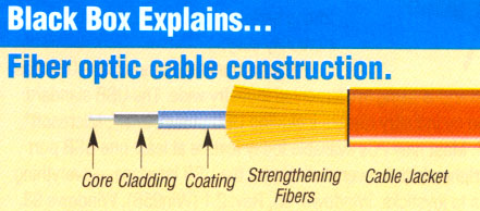
Fiber optic cable functions as a "light guide," guiding the light introduced at one end of the cable through to the other end. The light source can either be a light-emitting diode (LED)) or a laser. The light source is pulsed on and off, and a light-sensitive receiver on the other end of the cable converts the pulses back into the digital ones and zeros of the original signal. Even laser light shining through a fiber optic cable is subject to loss of strength, primarily through dispersion and scattering of the light, within the cable itself. The faster the laser fluctuates, the greater the risk of dispersion. Light strengtheners, called repeaters, may be necessary to refresh the signal in certain applications. While fiber optic cable itself has become cheaper over time - a equivalent length of copper cable cost less per foot but not in capacity. Fiber optic cable connectors and the equipment needed to install them are still more expensive than their copper counterparts. Single Mode cable is a
single stand of glass fiber with a diameter of 8.3 to 10 microns that has one
mode of transmission. Single-mode fiber gives you
a higher transmission rate and up to 50 times more distance than multimode, but
it also costs more. Single-mode fiber has a much smaller core than multimode.
The small core and single light-wave virtually eliminate any distortion that
could result from overlapping light pulses, providing the least signal
attenuation and the highest transmission speeds of any fiber cable type.
Multimode
fiber gives you high bandwidth at high speeds over medium distances. Light waves
are dispersed into numerous paths, or modes, as they travel through the cable's
core typically 850 or 1300nm. Typical multimode fiber core diameters are 50,
62.5, and 100 micrometers. However, in long cable runs (greater than 3000 feet
[914.4 ml), multiple paths of light can cause signal distortion at the receiving
end, resulting in an unclear and incomplete data transmission.
The use of fiber-optics was generally not available until 1970 when Corning Glass Works was able to produce a fiber with a loss of 20 dB/km. It was recognized that optical fiber would be feasible for telecommunication transmission only if glass could be developed so pure that attenuation would be 20dB/km or less. That is, 1% of the light would remain after traveling 1 km. Today's optical fiber attenuation ranges from 0.5dB/km to 1000dB/km depending on the optical fiber used. Attenuation limits are based on intended application. The applications of optical fiber communications have increased at a rapid rate, since the first commercial installation of a fiber-optic system in 1977. Telephone companies began early on, replacing their old copper wire systems with optical fiber lines. Today's telephone companies use optical fiber throughout their system as the backbone architecture and as the long-distance connection between city phone systems. Cable television companies have also began integrating fiber-optics into their cable systems. The trunk lines that connect central offices have generally been replaced with optical fiber. Some providers have begun experimenting with fiber to the curb using a fiber/coaxial hybrid. Such a hybrid allows for the integration of fiber and coaxial at a neighborhood location. This location, called a node, would provide the optical receiver that converts the light impulses back to electronic signals. The signals could then be fed to individual homes via coaxial cable. Local Area Networks (LAN) is a collective group of computers, or computer systems, connected to each other allowing for shared program software or data bases. Colleges, universities, office buildings, and industrial plants, just to name a few, all make use of optical fiber within their LAN systems. Power companies are an emerging group that have begun to utilize fiber-optics in their communication systems. Most power utilities already have fiber-optic communication systems in use for monitoring their power grid systems.
jump to Illustrated Fiber Optic Glossary pages
Fiber by John MacChesney - Fellow at Bell Laboratories, Lucent Technologies
Some 10 billion digital bits can be transmitted per second along an optical fiber link in a commercial network, enough to carry tens of thousands of telephone calls. Hair-thin fibers consist of two concentric layers of high-purity silica glass the core and the cladding, which are enclosed by a protective sheath. Light rays modulated into digital pulses with a laser or a light-emitting diode move along the core without penetrating the cladding. The light stays confined to the core because the cladding has a lower refractive index—a measure of its ability to bend light. Refinements in optical fibers, along with the development of new lasers and diodes, may one day allow commercial fiber-optic networks to carry trillions of bits of data per second.
Total internal refection confines light within optical fibers (similar to looking down a mirror made in the shape of a long paper towel tube). Because the cladding has a lower refractive index, light rays reflect back into the core if they encounter the cladding at a shallow angle (red lines). A ray that exceeds a certain "critical" angle escapes from the fiber (yellow line).
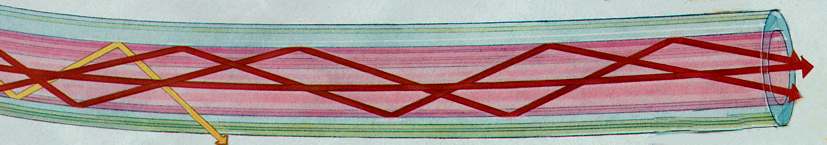
STEP-INDEX MULTIMODE FIBER has a large core, up to 100 microns in diameter. As a result, some of the light rays that make up the digital pulse may travel a direct route, whereas others zigzag as they bounce off the cladding. These alternative pathways cause the different groupings of light rays, referred to as modes, to arrive separately at a receiving point. The pulse, an aggregate of different modes, begins to spread out, losing its well-defined shape. The need to leave spacing between pulses to prevent overlapping limits bandwidth that is, the amount of information that can be sent. Consequently, this type of fiber is best suited for transmission over short distances, in an endoscope, for instance.
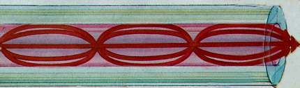
GRADED-INDEX MULTIMODE FIBER contains a core in which the refractive index diminishes gradually from the center axis out toward the cladding. The higher refractive index at the center makes the light rays moving down the axis advance more slowly than those near the cladding. Also, rather than zigzagging off the cladding, light in the core curves helically because of the graded index, reducing its travel distance. The shortened path and the higher speed allow light at the periphery to arrive at a receiver at about the same time as the slow but straight rays in the core axis. The result: a digital pulse suffers less dispersion.
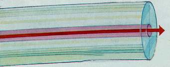
SINGLE-MODE FIBER has a narrow core (eight microns or less), and the index of refraction between the core and the cladding changes less than it does for multimode fibers. Light thus travels parallel to the axis, creating little pulse dispersion. Telephone and cable television networks install millions of kilometers of this fiber every year.
1 - Two basic cable designs are: 2 - Loose-Tube Cable
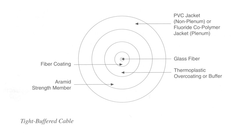
3 - Tight-Buffered Cable
Connector Types
Gruber Industries cable connectors
jump to Telebyte Fiber tutorial pages
2. The Fiber Optic Data Communications Link For the Premises
Environment jump to
The Complete
Telebyte Fiber tutorial pages
jump to
related fiber optic equipment pages
|
|